 Michael Griffis
Senior Lecturer
Mechanical and Aerospace Department
University of Florida
(email: mwg@ufl.edu)
Michael Griffis
Senior Lecturer
Mechanical and Aerospace Department
University of Florida
(email: mwg@ufl.edu)
AREAS OF SPECIALIZATION
My areas of specialization span across the mechanical engineering, electrical engineering, and computer science disciplines. This wide span is largely due to when and where I started my graduate research in the field of robotics (mid 80s at CIMAR) and what I did afterwards in industry (20 years). Robotics demands expertise in these areas. In each of these areas, I have practical, hands-on experience due to the necessity of designing and building a particular functioning system. And, I have theoretical experience due to the necessity to model some complex robotic system.
For the mechanical engineering aspect, I specialize in mechanical design, both synthesis and analysis, structural design, kinematics, mechanisms, geometry, screw theory, servo-controlled systems, both force and position. I have designed and built robot actuators of the electro-mechanical, hydraulic, and pneumatic variety.
For the electrical engineering aspect, I have designed and built power supplies and power amplifiers. I have developed a foliage penetrating radar. I specialize in designing circuits for Electromagnetic Compatibility (EMC). I specialize in Field Programmable Gate Arrays (FPGA) and designing devices for the Universal Serial Bus (USB). I specialize in all kinds of robotic sensors, force, Light Detection and Ranging (LIDAR), ultrasonic ranging, camera, and video. I specialize in robotic navigation systems, Global Positioning Systems (GPS), Real-time Kinematic (RTK) GPS, Inertial Navigation Systems (INS), Attitude Heading Reference Systems (AHRS), sensor fusion, and Kalman Filters.
For the software engineering aspect, I do specialize in writing robotic software applications for larger systems. But I primarily focus on embedded control systems, which are dedicated purpose machines. I specialize in microcontrollers, Digital Signal Processing (DSP), Advanced RISC Machine (ARM) Processors, and image processing.
One encompassing area that I specialize in is robot safety. This involves emergency stop circuits, safety circuits, and the safeguarding of robots to make them safe for users.
Another encompassing area that I specialize in is product development. This involves design process theory, intellectual property, codes and standards, designing for manufacture and assembly, and product safety.
Developing a Capstone Design Program
Industry Involvement and Feedback on Approach
My idea for a “Capstone Design Program” originated during efforts to build greenhouse tables for the College of Medicine’s Wilmot Gardens in 2013 (Section 11.4 below). Students thoroughly enjoyed working on projects where we were improving the quality of life of an elderly person or a person with a disability.
As a matter of fact, I explicitly ask the students “how can we improve the quality of life of this person?” I encourage the students to avoid using cost and simplicity as goals and to really push new technology to create innovative designs.
The history of my design projects are detailed below, and one can see that there were detours for various reasons away from an “assistive technology” slant. Based on what follows, I hope it is clear that we have developed a cohesive program to build new and exciting “assistive devices” to improve the quality of life of persons with disabilities.
Last year I reached out and met Tony Delisle and Mark Brisbane from Center for Independent Living (CIL) located near the UF campus. Mark is actually a quadriplegic who has some use of his arms. Tony (legally blind) is the Director. They are shown in Figure 1.
I became intrigued with the possibility of building assistive devices. My entire Design 3 (Fall 2018) class went to CIL and met with three “customers” or “users” who we interviewed for our project. (The reader can view this in our video Here.) The customers gave us direction as we designed our reacher.
Recently, Mark from CIL inspired me to attempt to build an exercise machine for quadriplegics. There was an old exercise machine design called the “Uppertone” but the company that made this device had recently gone out of business. One of the owners of that company, a quadriplegic himself, recently died. For my current class (Spring 2019), we are working on this project and I needed to obtain an existing Uppertone for benchmarking. These machines are not available for purchase anywhere (used or new). It turns out that Shands Rehab actually has one, and they let us borrow it for one week.
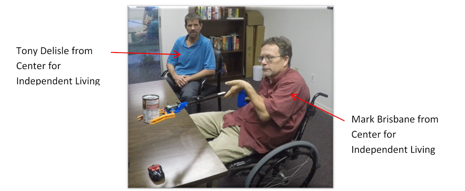
Figure 1. Tony and Mark from CIL
Our current goal is to build a modern Uppertone that pushes technology and uses all of the latest exercise theories. It is interesting that this is now a hot topic. After I spoke to the remaining living owner of the former company, I became aware of other interested folks. A physician, Glen House MD, from Colorado has reached out to us about our project. He is himself a quadriplegic and is interested in this field. He is interested in forming a company to sell a new Uppertone.
The assistive device field is exciting, rewarding to the end-user and to the student designers. I feel this is a very rich field to focus on. Thus, I hope it is clear that I have developed a cohesive, long term program for “capstone design” which pushes technology in order to create assistive devices. It is something that the students are buying into, since they are very selective where they place their energy.
The course Mechanical Design 2 (EML4501), or just “Design 2” for short, is a capstone design course. Recently, it became the first of two capstone design courses. I teach this particular capstone design course as Introduction to Product Development, which technically is *not* how the course was introduced to me in 2012 when I first taught it. When I first “got the keys” to this course, I found it to be a hodge-podge of topics that lacked some cohesiveness. I feel like one of my major contributions is honing and expanding the topics covered and tailoring the result towards teaching how to develop an actual product.
Historically, the course focused on “reverse engineering” a small product (like a tire gauge) and then a more comprehensive product (like a rotisserie). Historically, topics included the following:
I kept these topics and added additional ones that collectively formed the basis for product development:
The sum total of these topics allowed me to rename the historic “reverse engineering study” to a more encompassing and enriching “feasibility study.” Basically a feasibility study of a potential product identifies how feasible it is to manufacture a product, e.g. in the US.
There are a few guiding principles that I rely on when I teach the course. These set a firm foundation for the student, as I try to teach them how to design. The first is the Design Process and the second is the Design Stool. Each of these is discussed thoroughly in Section 9 of this document.
Directing the students in these design projects consumed so much of my time. Thus, I think it is worthwhile discussing the various final projects for this course. Also, as discussed above, it is the objective to carryover the results of the final projects of this course and use them in the new, follow-on course (Design 3). For the final project, the students are typically segregated into groups of 6 to 8 students. The following table is an overview of the terms when I have taught this course.
|
Term |
Sections |
Students |
Design Groups |
Group Size (Ave) |
Project |
|
Spring 2019 |
2 |
130 |
18 |
7-8 |
Exercise Machine for quadriplegic |
|
Spring 2018 |
1 |
134 |
18 |
7-8 |
Articulated Reacher for someone with a disability |
|
Fall 2017 |
1 |
125 |
16 |
7-8 |
Autonomous Hydrofoil (co-taught with Dr. Ifju) |
|
Fall 2016 |
1 |
147 |
24 |
6-7 |
Solar Tracking Robot |
|
Spring 2016 |
1 |
110 |
18 |
6-7 |
Stirling Engine Cell-phone charger |
|
Fall 2015 |
1 |
101 |
17 |
6 |
Articulated Weeder for therapeutic horticulture |
|
Spring 2015 |
1 |
111 |
18 |
6 |
Articulated Reacher for someone with a disability |
|
Spring 2014 |
1 |
112 |
22 |
5-6 |
Battery-powered portable trashcan |
|
Fall 2012 |
1 |
75 |
14 |
5 |
Rotisserie |
In order to set the stage for the reader, I am identifying the NEED for each of these terms and at times providing a representative image of student’s work. I established the need for the groups and then coached the students to create their designs.
Spring 2019. Articulated Power-assisted Uppertone (upper-body exercise machine for a quadriplegic)
The sole existing upper-body exercise machine for a quadriplegic was the historic “Uppertone” but after 30 years, it is no longer being manufactured. Basically, there is now a NEED for an Articulated Power-assisted Uppertone, which is a new exercise machine for a quadriplegic. Articulated means it can move in multiple directions as needed by the user for various exercises. Power-assisted means it can operate in one of two modes: (i) it can safely guide the user through the selected exercise (assistive) or (ii) it can provide programmable resistance to the user to effect the exercise (resistive). A combination of these modes during different segments of an exercise is also a possibility. The Power-assisted aspect denotes an electro-mechanical, forced-controlled solution. The new Uppertone must maintain the ability for the quadriplegic to independently set up the machine when used at home. Note that depending on the spinal injury, some quadriplegics do have limited arm and hand mobility. While this project is for those folks, it is important to remember that such a quadriplegic has limited hand dexterity. The machine could be used at home or in a physical therapist’s gym. See Figure 2.
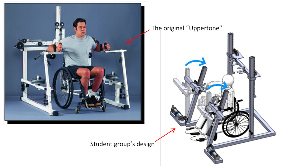
Figure 2. Exercise Machine for Quadriplegics
Spring 2018, Spring 2015. Articulated Reacher (a grasping aid for the elderly or persons with a disability)
There is a NEED for a “reacher” that enhances the reach of an elderly person or a person with a disability. It should be more dexterous and more sensitive. It should enable a more secure grasp. It should have more workspace, range of motion. It should be articulated. It should be able to retrieve more things. It should be power assisted. The project assumes there is some “gripping function” and some “articulation function” which are features of the design. The students used existing ones (like the one sold by Harbor Freight) for benchmarking. See Figure 3 for a student group’s design of the articulated reacher. This reacher was very close to our first prototype built in Fall 2018 (Design 3).
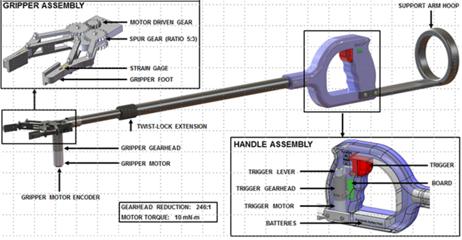
Figure 3. EML4501 Version of Articulated Reacher (Spring 2018)
Fall 2017. Unmanned Hydrofoil Vehicle
There is a NEED for an unmanned surface vehicle (USV) that
· uses a hydrofoil to lift its hull out of the water to reduce drag and allow faster speed
· is powered by rechargeable batteries
· is capable of remote control as well as autonomous waypoint navigation
· exhibits longitudinal and lateral stability
· rides at a desired elevation above the mean water level (in light chop)
· performs smooth, controlled turns as necessary
· has a top speed of 30 mph (26 knots)
· has an endurance of 2 hours at 23 mph (20 knots).
This course was team taught with Dr. Ifju. The need was written by him. I supported the class by instructing how to build the drive train. See Figure 4 which shows the Spring 2018 Design 3 implementation (pre-flight) and Figure 5, which shows its first flight.
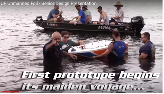
Figure 4. Before Autonomous Hydrofoil First Flight (image from Spring 2018).
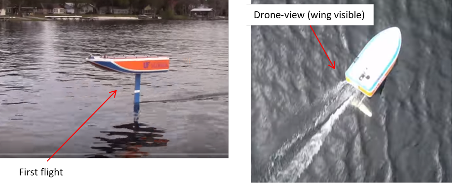
Figure 5. Actual Hydrofoil in action (designed Fall 2017, image from Spring 2018)
Fall 2016. Articulated Solar Tracker Charger
Consider a human-powered craft (bicycle, velomobile,
kayak, canoe, pedal boat, etc.) where some electrical power (![]() from 3
USB connectors) is desired. Imagine it is a clear sunny day.
from 3
USB connectors) is desired. Imagine it is a clear sunny day.
·
There is a NEED for ![]() of electrical power
from a deployable, articulated solar tracker that can be mounted on the
vehicle. The objective is to provide
of electrical power
from a deployable, articulated solar tracker that can be mounted on the
vehicle. The objective is to provide ![]() continuous at
continuous at ![]() so
that the occupant(s) can charge cell phones, power a small computer, GPS, camera,
etc.
so
that the occupant(s) can charge cell phones, power a small computer, GPS, camera,
etc.
· There is a NEED for the tracker to deploy the device above the occupants.
· There is a NEED for the tracker to autonomously articulate as the vehicle moves to maintain optimal solar rays on the device.
The groups were given a solar tracker model for benchmarking. My instructional depiction is shown in Figure 6.
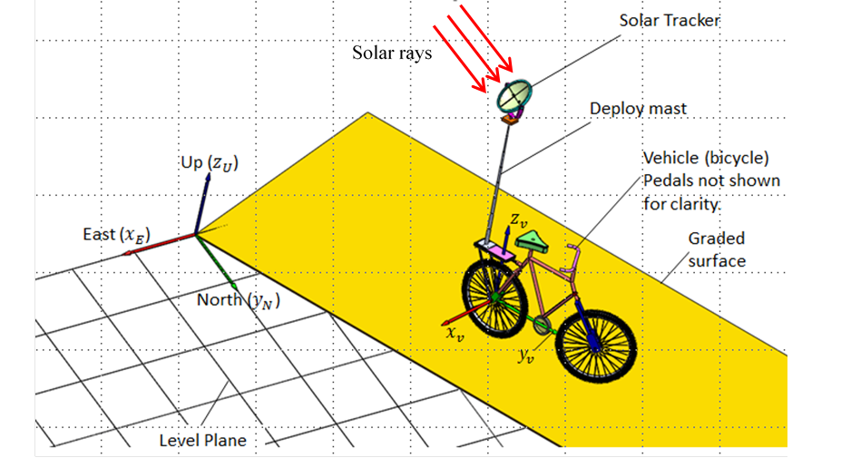
Figure 6. Solar Tracking Robot Classroom discussion example (Fall 2016)
Spring 2016. Stirling Engine Charger
There is a NEED for a Stirling engine that is
portable and generates up to ![]() of power, so that the operator
can charge a modern cell phone. The groups were given a functional Stirling
engine model. See Figure 7 for an example of a student group’s concept.
of power, so that the operator
can charge a modern cell phone. The groups were given a functional Stirling
engine model. See Figure 7 for an example of a student group’s concept.
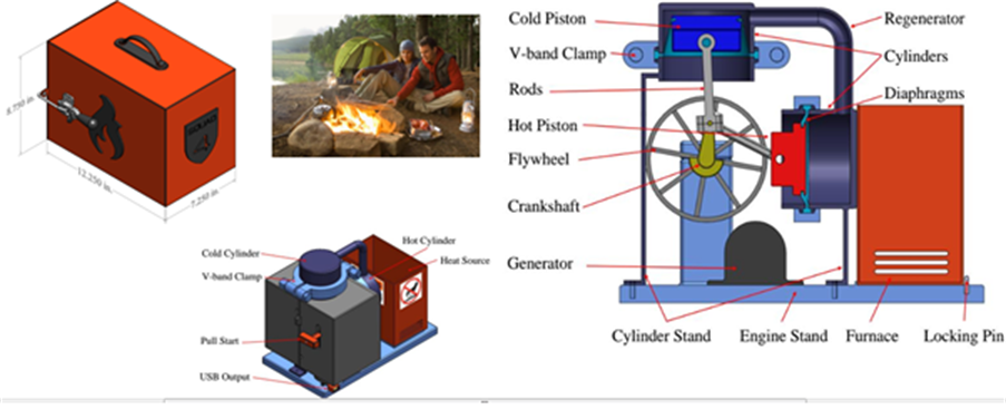
Figure 7. Student Group's Stirling Engine Charger Design (Spring 2016)
Fall 2015. Articulated Weeder
There is a new field called “therapeutic horticulture”. A person with a disability may enjoy gardening but is not able to. There is a huge opportunity to improve someone’s quality of life. As such, there is a NEED for a weed pulling “weeder” that enhances the capability of a person with a disability:
· more dexterous (more mobility)
· more sensitive
· more workspace, range
· articulated (user input one place, effecting output another place)
· can do more things (also pruning?)
· power assisted.
The students used the Fiskar’s weeder for benchmarking. Figure 8 shows Mark Ford who is a paraplegic using the prototype “Articulated Weeder.” This particular project was inspired by the Wilmot Gardens project (discussed below).
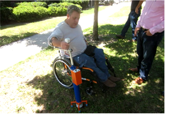
Figure 8. Mark Ford (user) test driving prototype "Articulated Weeder"
Spring 2014: “Automatic Trash Krusher”
There is a NEED for a portable “automatic trash krusher” that
Note: this project relied on an inventor who brought experience of manufacturing in China to our classroom. The students used the inventor’s manual version for benchmarking.
Fall 2012. Rotisserie
There is a NEED for a rotisserie that was small, efficient, fast, and autonomous. The students used the Ronco version for benchmarking. For me, this project was especially challenging, since heat transfer is not my forte. However, I applied the same guiding principles to myself as I led the class on this project (Figure 9).
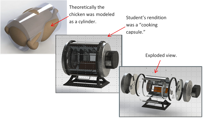
Figure 9. Capstone Design Project--Rotisserie (Fall 2012)
The course Mechanical Design 3 (EML4502), or just Design 3, was created in 2015 and actual sections began in 2016. I have taught this course three times and I am gearing up for another go (Fall 2019). The students and I have learned together what works and what does not, as the following explains.
Fall 2016. My first section was Fall of 2016 when I had 10 students. These students built the Stirling Engine Charger (from Design 2’s Spring 2016). Our first challenge was that the “Senior Design Lab” was under construction and would not be completed during the semester. Our second challenge was that we split the 10 students into two groups of five. The two groups built different engines. The “student person-power” was not enough.
The goal that I had was admirable, which was keep groups small and let the students architect the total solution. In other words, one of the students from each team was that team’s “Chief Architect.”
Spring 2017. This was my second section when I had 26 students. We created three groups of 8 to 9 students each in order to have better support. These students built the Solar Tracking Robot (from Design 2’s Fall 2016). Each group built their own version of the robot.
During this term, I focused on fine tuning the roles that each student would play. The “Chief Architect” role remained and one of the students from each group tried to fill it. I now know it was too much to expect a student to play this role.
Fall 2018. This was my latest completed term when I had 19 students. Collectively, we built one design as the following describes. This term we built the “Articulated Reacher” since it followed Design 2’s Spring 2018.
When we created groups, we did so based on lab sections. Each lab section was assigned a particular subsystem. There were three lab sections, so we created three subsystems: handle, extension, and gripper. The teams had 5 to 8 students each, so the teams were of reasonable size (not too big).
This and the fact that I now played the role of “Chief Architect” were the needed changes to realize success in the course. Figure 10 shows the finished product in use by Mark Brisbane of Center for Independent Living.
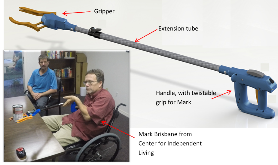
Figure 10. Fall 2018 Articulated Reacher (Mark from CIL using the realized reacher Dec 2018)
Bio-design (ASME) for me began in 2013 when I started the Wilmot Garden’s project. It was at that time that the College of Medicine was building the new greenhouse at the South-end of Gale Lemerand Drive. Our goal was to build a special kind of greenhouse table that adjusted to the height of the person using it. The greenhouse was opened to support “therapeutic horticulture,” which used gardening to provide therapy. One particular facet of this was the intended user would be a person with a disability. Such a person would need an adjustable table to maneuver to an optimal height. It was a great design project for us, and we created and delivered two versions of the table (approximately 10 tables total). They are in use today. See Figure 11.
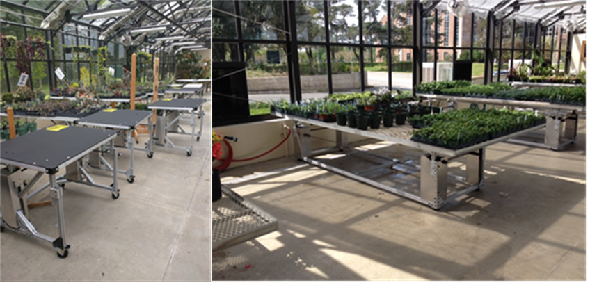
Figure 11. Our greenhouse tables at Wilmot Gardens
The concept of therapeutic horticulture intrigued me and inspired me to develop the program for Capstone Design (see 11.1 above). I found that the students enjoyed the project and the anticipated joy of the end user was inspiring.
Another recent activity along these lines regards designing a surgical table for Dr. Oliver Horne, College of Medicine. Dr. Horne is a heart surgeon who has limited use of his left arm. We designed a special “Cardiac Table” for him. See Figure 12. We are currently building a second version of this.
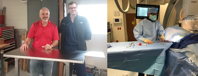
Figure 12. M. Griffis, Dr. Horne and the "Cardiac Table"
With regard to involvement with industry, I am very fortunate to receive the support of Cummins and Northrup Grumman in sponsoring our Capstone Design Program. They provide significant financial support to us. And additionally, and perhaps more importantly, they send engineers to review our students work. These industry engineers sit through our design presentations and then work with me to give the students important, realistic, real-world engineering feedback.
Additionally, it happens that I get a lot of positive feedback from former students, who have gone into industry and done well. One student is Danny Carballo (GE Appliances). He wrote an unsolicited email to me a few years ago that is typical in most respects. There are a few key differences. First, Danny references a positive interaction with the CEO of GE Appliances. Also, when he was a student, Danny and I did not always see eye-to-eye, so I especially enjoyed seeing his email. (I remember encouraging him to do more in his theoretical analysis.) Anyway, I am presenting the email (Figure 13) here un-edited and representative of what I get.
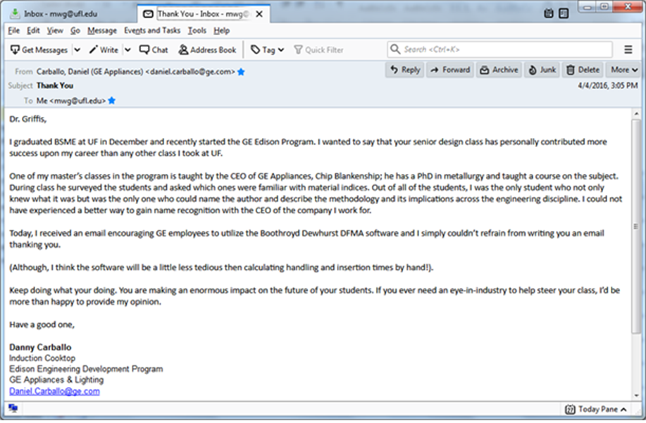
Figure 13. Email from former student (now at GE Appliances).
As a creative activity to improve and supplement my teaching, I have created numerous videos, each of which is painstakingly edited in an attempt to create professional engineering presentations. I started doing this in Fall 2013. Using a personal laptop and a personal copy of Camtasia, I have been able to create what I hope are good videos. The students are watching them and they have been positive. Recently, starting late Fall 2018, I started uploading some of the videos to Youtube. My Youtube channel link is Here.
The following describes some of the videos that I have done. The ones shown here are self-contained videos, in the sense that each explains the engineering context and tries to be comprehensive and complete, so that any engineer could follow it. Other videos that I have done (not listed here) are extensions of what was started in lecture, so those would only make sense to the students who took the associated class.
|
|
Title |
Length (minutes) |
Goals |
|
1 |
Bolts in Solidworks |
24 |
Shows how to use Solidworks to design bolted connections. |
|
2 |
Clothes Pin: Solidworks Motion Analysis Example |
21 |
Shows how to use Solidworks to model contact with simple clothes pin example. |
|
3 |
Compound Lever |
20 |
Shows theory behind combining two simple machines into one compound machine. |
|
4 |
Product Development and Realization: Engineering Roles |
21 |
Discusses first attempt (Spring 2017) to establish engineering roles in the EML4502 course. |
|
5 |
Tolerancing Example |
17 |
Uses the Harbor Freight clamp (foot) to ponder tolerancing and fit. |
|
6 |
Exercise Machine: Mechanics |
11 |
Discusses resistive-vs-assistive modes a machine might use to help the user during an exercise |
|
7 |
Patents |
39 |
Discusses important aspects of patenting an invention and uses the exercise machine as an example. |
|
8 |
Genesis of Principal Stresses |
10 |
Discusses principal stresses in mechanical engineering. |
|
9 |
Human Factors (2019) |
22 |
Discusses the MIL-1472 spec on human factors (engineering with the human involved). |
|
10 |
|
9 |
Enlightens the engineering student about the differences between a “pound mass” and a “pound force.” |
|
11 |
Motion Analysis Example: Gearing |
33 |
Does a Solidworks motion study of a pair of gears. |
|
12 |
Plane Stress |
7 |
Discusses the special case of plane stress in mechanical engineering |
|
13 |
Material-ID: Plastics Example |
31 |
Explains how to discover what kind a material something is made out of |
|
14 |
Programming in Mechanical Design |
52 |
Takes some simple equation and programs it in three different programming languages (Matlab, Mathematica, Excel) |
|
15 |
Screws and Wedges |
16 |
Gives simple machines theory |
|
16 |
Sig. Figs. |
18 |
Discusses significant figures (digits) for mechanical engineers |
|
17 |
Solar Tracker Power |
16 |
Discusses design of a power supply for a solar tracking robot. |
|
18 |
Solidworks FEA |
59 |
Discusses using “finite element analysis” (FEA) in Solidworks |
|
19 |
Planar Robot Kinematics: Fun with Solidworks |
47 |
Discusses a simple robot that is simulated in Solidworks. |
|
20 |
Success and Failure in Design |
28 |
Discusses the Design Process in mechanical engineering |
As a creative activity to improve and supplement my teaching, I created what I call “webgems,” a word that originated on a cable sports network. It was catchy, so I adopted it in the classroom to convey to the students how an activity would be done. They quickly caught on.
Basically, a webgem is a program that I wrote that runs on my office computer. To be more specific, it runs on a webserver on my office computer so that students can access the program remotely. Generally speaking a webgem ensures that a student
While the webgems are equivalent in difficulty between any given students, each webgem is individualized so that no two students get exactly the same webgem. Thus, while students might work together, this ensures that each student understands their own webgem.
The following are screenshots and descriptions of an example webgem. This particular webgem is for “1-D Static Failure in Structures” that makes sure the student understands simple one-dimensional static failure of a structure. For example, the student is shown Figure 14 to set the stage. Then the student progresses through the webgem by answering questions (Figure 15). Once all questions have been attempted (Figure 16), the student can decide to record or “finalize” the webgem. Once it has been finalized, Figure 17, the student is done but could attempt a fresh webgem with the “New” feature.
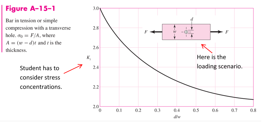
Figure 14. The figure used in the example webgem.
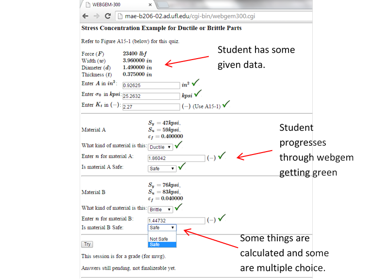
Figure 15. Student progressing through webgem.
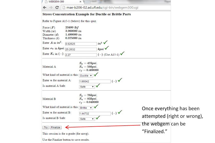
Figure 16. A finalize-able webgem where all questions have been attempted.
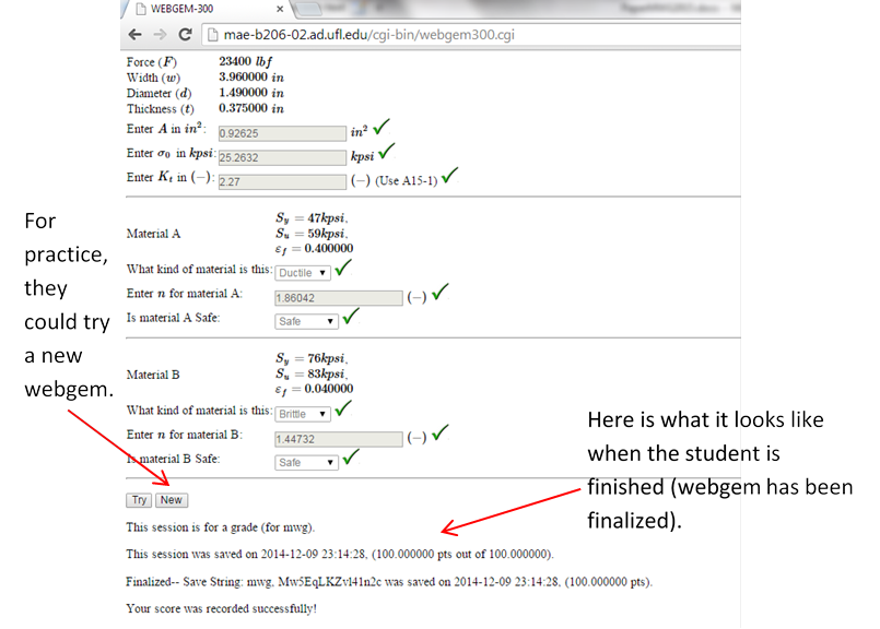
Figure 17. A webgem that has been finalized.
The preceding explains what a webgem is and how I might use one. The following table highlights the various webgems that I have written over the years (starting in Fall 2013).
|
|
Webgem title |
Goals |
|
1 |
Hello World |
Gets the student acquainted to a webgem (easy). |
|
2 |
Mobility of mechanisms |
Checks understanding of whether and how a machine can move. |
|
3 |
More Mobility |
Checks understanding of whether and how a machine can move. |
|
4 |
Four-bar example |
Checks understanding of simplest known linkage. |
|
5 |
Body Guidance |
Checks understanding of how a body can move in planar motion. |
|
6 |
3R Robot Position |
Checks understanding of position control of a simple planar robot. |
|
7 |
3R Robot Velocity |
Checks understanding of the velocity state of a simple planar robot. |
|
8 |
3R Robot Torques |
Checks understanding of the joint torques of a simple planar robot. |
|
9 |
3R Joint Forces |
Checks understanding of the joint forces of a simple planar robot. |
|
10 |
Materials--selection |
Checks basic understanding of materials (mainly metals) |
|
11 |
1D Static Failure in Structures |
Checks understanding of whether a simply loaded part will fail. |
|
12 |
Principal Stresses in Structures |
Checks understanding of principal stresses (main stresses) in a part that sees complex loading. |
|
13 |
Combined Stress in Structures |
Checks understanding of how stresses combine in a part that sees complex loading. |
|
14 |
Design Process |
Checks understanding of the abstract design process |
|
15 |
Units & Significant Figures |
Checks understanding of units and significant figures (digits). |
|
16 |
Bolts--design |
Checks understanding of how to select bolts, nuts in a bolted connection. |
|
17 |
Welds |
Checks understanding of how to design a welded joint. |
|
18 |
Bearings-sleeve-ball-roller |
Checks understanding of selecting a sleeve bearing, a ball bearing, and a roller bearing for various situations. |
|
19 |
Gears-spur |
Checks understanding of spur gears where the rotation axes are parallel. |
|
20 |
Gears--worm |
Checks understanding of worm gears where the rotation axes are perpendicular and offset and where a high reduction occurs. |
|
21 |
Fatigue--Stress-Life |
Checks understanding of the stress-life theory on a part that undergoes cyclic loading. |
|
22 |
Fatigue--Modified Goodman |
Checks understanding of the stress-life theory on a part that undergoes fluctuating loading. |
|
23 |
Shaft Design |
Checks understanding of designing a shaft (for example, the one shown below in Figure 19) |
|
24 |
Simple machines |
Checks understanding of simple machines (for example, the ones used in the Rube Goldberg robot shown below) |
|
25 |
Screws, wedges, compound machines |
Checks understanding of compound machines (for example, the several used in the Rube Goldberg robot shown below) |
A few comments might be helpful to understand the motivation behind writing these webgems. First, assigning homework problems out of the book is a non-starter, since the students have a copy of the solution manual from the Internet. Secondly, even if I were to tweak those problems, they are too trivial and easy. Plus everyone in the class could compare numbers. Secondly, I tried to use McGraw-Hill’s Connect program that randomly generates questions (changes numbers) for the students. I also was not satisfied with this for the triviality reason. Students were not learning and they were not able to do involved calculations or master basic theory. A third reason was I could write the programs, since I have written many different kinds of computer programs. I was able to interface with Canvas, so that the webgem loaded into the student’s homework assignment and uploaded their webgem hyperlink. Canvas has an API (application programming interface) that makes this possible.
Regarding the Canvas API, I have considered maturing the webgem more and actually creating online quizzes automatically in order to achieve similar results. I have been experimenting with this recently, especially after I discovered that the Canvas system supports LaTeX, which is a markup language that handles math. I have recently been using the Canvas quizzes during class as an “activity” to make sure the students are capturing the technical nugget of the day.
In my recent semesters of teaching Mechanical Design 1 (EML3005), or just “Design 1,” my approach has matured. I split the course into three or four segments that were indicative of the nature of the course:
It should be mentioned that (as far as I know) I have been the only instructor to teach kinematics in this course. Furthermore, it should be noted that kinematics has been removed from our curriculum as a dedicated course.
The students were placed into groups to conduct projects in each segment of the course. During this era, the students submitted design reports. The following data highlights the relevant semesters during this era.
|
Term |
Sections |
Students |
Design Groups |
Group Size (Ave) |
Format |
|
Spring 2018 |
1 |
71 |
19 |
3-4 |
One project |
|
Fall 2017 |
1 |
80 |
23 |
3-4 |
One project |
|
Spring 2017 |
2 |
127 |
N/A |
Individual |
6 projects |
|
Spring 2016 |
1 |
54 |
N/A |
Individual |
7 projects |
|
Fall 2015 |
1 |
100 |
50 |
2 |
Three projects |
|
Spring 2015 |
1 |
52 |
26 |
2 |
Three projects |
|
Fall 2014 |
2 |
158 |
79 |
2 |
Four projects |
The objective of this era of the course was to encourage the students to do simulations in order to bolster and validate their analytical theory. As far as I know this had not been done before. We use Solidworks, which is their CAD (computer-aided design software), to do the simulation. Generally, this was a huge challenge for the students but many felt very enthusiastic when their Solidworks simulation matched their theoretical results.
For example, one of the educationally critical projects involved redesigning a vintage 60s Ford Mustang 4-speed manual transmission (started in Fall 2014). As far as I know, no instructor has attempted a project like this. I had a vintage version of the transmission that I brought to class. The students changed the gear ratios for the transmission and designed their own version. They did their own Solidworks design and then used their CAD images to do “conceptual art” (Figure 18) and “analytical art” (Figure 19).
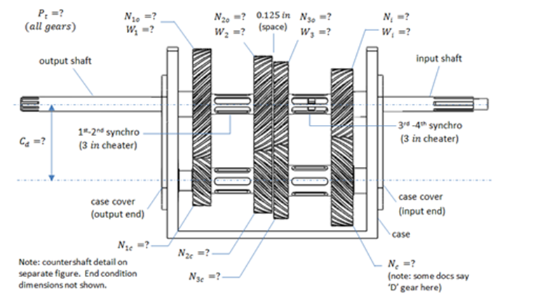
Figure 18. Redesign of 60s Ford Mustang 4-speed transmission (Conceptual Art).
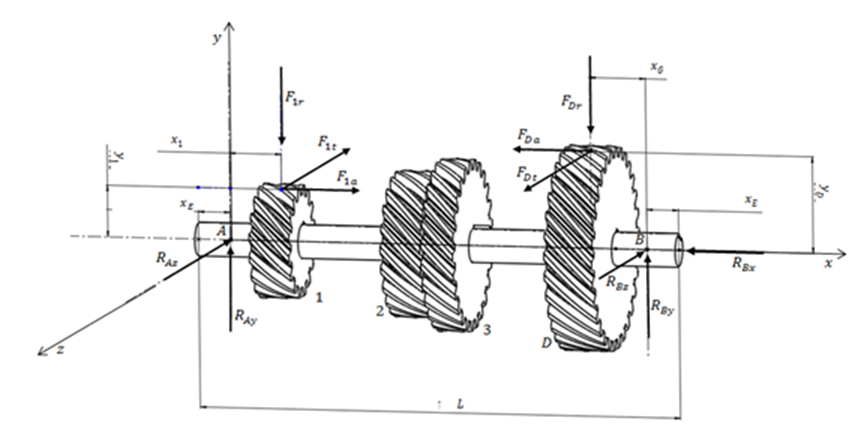
Figure 19. Redesign of 60s Ford Mustang 4-speed transmission countershaft (Analytical Art).
The students were able to prove their theory was right by doing simulation (Figure 20). While this was actually pretty tricky to simulate, almost all students have been successful in doing this project (attempted almost every semester of the “modern” era). The students learned a lot about gearing, bearings, shafts, and how to attaching components to shafts.
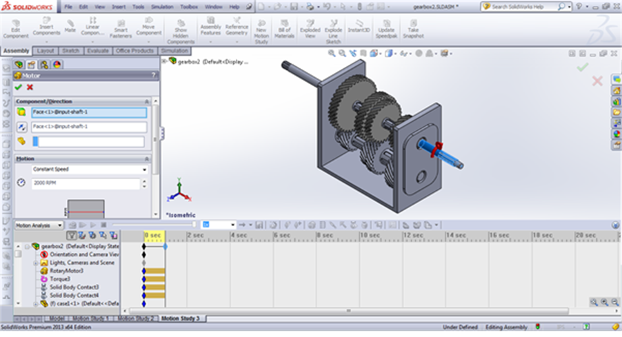
Figure 20. Redesign of 60s Ford Mustang 4-speed transmission (Simulation in Solidworks).
Another example was a robotic pallet jack, which was first accomplished by the students of Fall 2014. Figure 21 shows a conceptual view of what needed to be done, which is a large load (location A) needed to be placed on the truck bed (location B). What the students did can be seen in Figure 22 through Figure 26. The students created their own robot in Solidworks and then predetermined the angular displacement requirements on each of the three joints of the robot. This included allowing for the bed of the truck to dip (slightly) due to the load being accepted by the truck bed (Figure 25). Note that almost all students were successful in the semesters this was attempted (Fall 2014, Spring 2016, Spring 2017).

Figure 21. Conceptual drawing of need for robotic pallet jack.
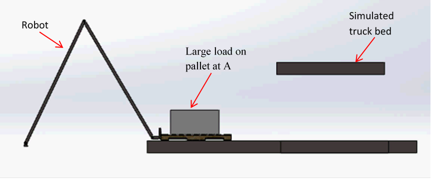
Figure 22. Solidworks design/simulation of robotic pallet jack (load at A).

Figure 23. Intermediate position of robotic pallet jack.
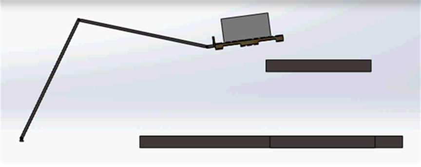
Figure 24. Intermediate position (two) of robotic pallet jack.

Figure 25. Intermediate position 3 or robotic pallet jack (gets load to location B).

Figure 26. Final position and robotic pallet jack has been extracted from load.
Another enriching robotic example was the very challenging walking bi-ped robot that had the students calculate what the joints of two legs needed to do in order to get the robot to walk over and sit down. See Figure 27. This was a very challenging project and about 2/3 of the students were successful (Spring 2015). In these types of projects, the students learned a lot about kinematics, geometry, quasi-static equilibrium.
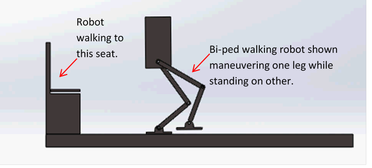
Figure 27. Walking bi-ped robot (Spring 2015).
Another educationally rich robotic example was the “Rube Goldberg” robot example shown in Figure 28 through Figure 31. This design project required the students to design a robot to move a load onto a shelf and then have the robot use at least one simple machine to get the load from the shelf onto a conveyor. The simple machine shown below has a screw that is turned by a crank and a pair of bevel gears (not identified in figures). This project was the most difficult that I attempted with the students. About one third of the students were successful. I think all students were able to the load onto the shelf and start the process of moving the load further using the simple machine. In addition to the kinematics, geometry, and quasi-statics, the students learned about designing with simple machines.
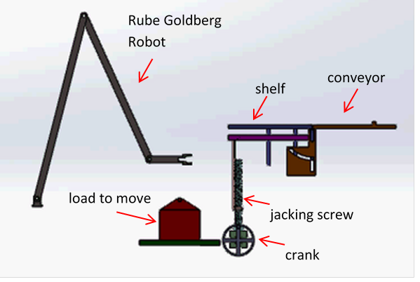
Figure 28. Rube Goldberg robot example (Fall 2015)
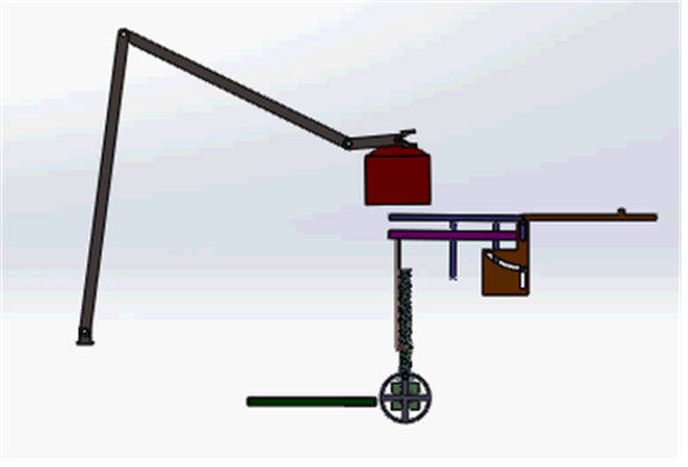
Figure 29. Rube Goldberg robot moving load to shelf.
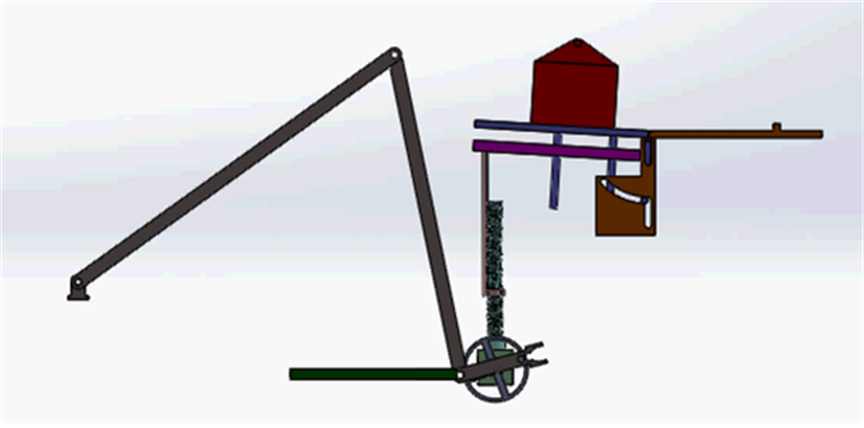
Figure 30. Rube Goldberg robot cranking screw to move load.
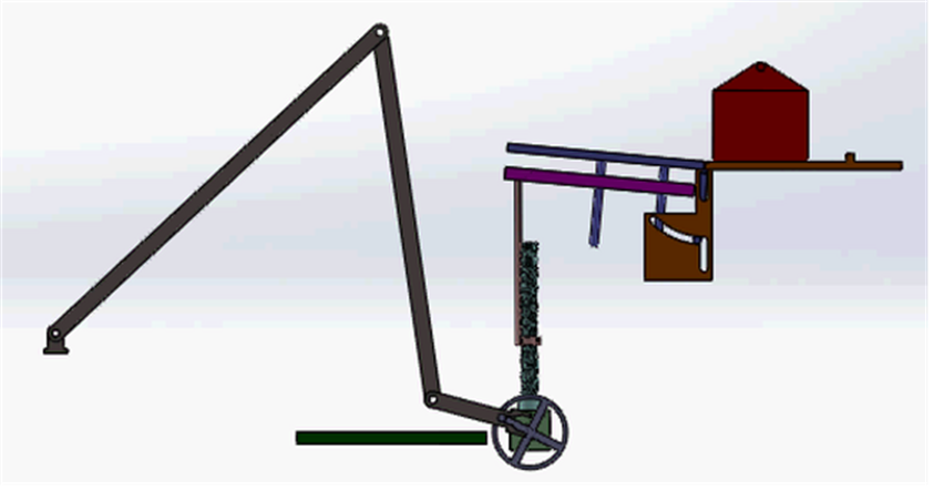
Figure 31. Rube Goldberg robot cranks until load transfers to conveyor.
The projects were enjoyable to a great many of the students and they were successful because the projects required the students to put into practice the theory they were learning in lecture. A final example shown in Figure 32 is from Spring 2018, which is a robotic gripper. This is a great example, because it uses gears, kinematics (geometry), a planetary gear box, worm gear assembly, and an electric motor.
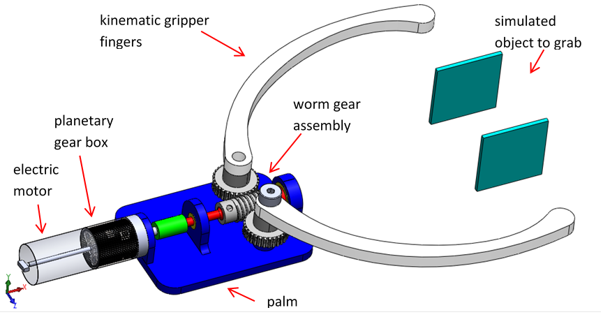
Figure 32. Robotic Gripper (Spring 2018)
In my early semesters of teaching Design 1 (EML3005), I covered the basic how-to’s of Design Process, mechanical components like gears, bearings, shafts, and finally kinematics which is the geometry of motion. The course had the traditional homework and exams supported by my videos and webgems.
In parallel with this, I also had the students do design projects in groups. I had the students submit reports for each step of the Design Process (need, requirements, creative synthesis, analysis, evaluation). It created a huge challenge to give feedback to the students, while maintaining their normal individual workload. This was extremely difficult because I allowed the groups to choose their own design, starting from the conception of the “need for something.” This meant that I had to keep track of a large number of different design projects. The table below shows the relevant terms, the number of students and number of groups.
|
Term |
Sections |
Students |
Design Groups |
Group Size (Ave) |
Format |
|
Spring 2014 |
1 |
84 |
22 |
4 |
Presentations and Reports |
|
Fall 2013 |
2 |
178 |
45 |
4 |
Presentations and Reports |
|
Spring 2013 |
2 |
182 |
46 |
4 |
Presentations and Reports |
|
Fall 2012 |
1 |
87 |
22 |
4 |
Report only |
|
Spring 2012 |
2 |
206 |
53 |
4 |
Report only |
|
Fall 2011 |
1 |
88 |
22 |
4 |
Report only |
I encouraged the students to be creative with their ideas and also be creative in their presentation of their ideas. Their design was art and so was the presentation of it. While the designs were not patentable, they did present engineering challenges for each of the undergraduates.
Starting in Spring 2013, I also had the groups do presentations. Each group gave a 30 minute presentation which was followed by a feedback discussion of how well they did. The objective here was to give them real-world feedback with a live engineering audience. When there were heavy semesters like in 2013, this would take three full days to conduct.
I encouraged some of the groups to do “computer-aided design” of their projects. During 2013, the students did the normal design art and then fulfilled their designs by computer generating them. For example, in Fall 2013, a group designed a “tooth brush robot” that is shown in Figure 33. And in Spring 2013, a group designed a “Sky Beam” to carry a large load, which is shown in Figure 34.
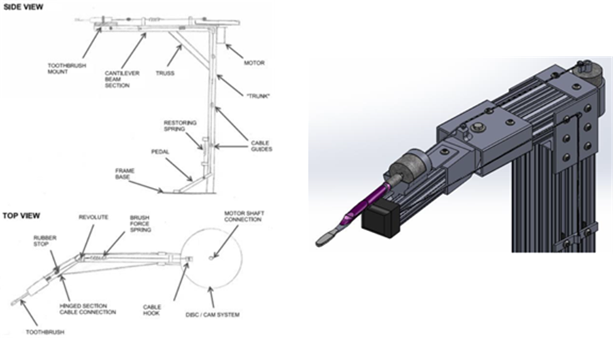
Figure 33. Design and computer-aided design of a tooth brush robot (Fall 2013).
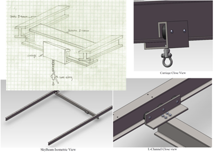
Figure 34. Design and computer-aided design of a "Sky Beam" (Spring 2013)
Figure 35 shows an example taken from Fall 2012. The group designed a winch to allow the wakeboard skier to control the length of ski rope.
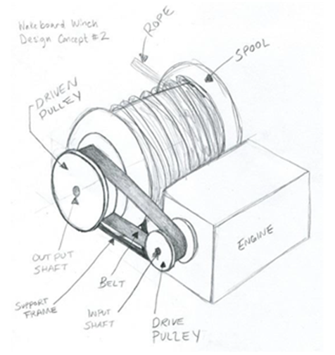
Figure 35. Wakeboard winch to allow skier to control ski rope length (Fall 2012).
Below is an example taken from the semester Spring 2012. Figure 36 shows a group’s idea to put a suspension on the front of their solar powered car.
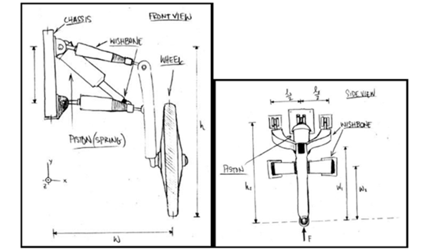
Figure 36. Front suspension design for a solar powered vehicle (Spring 2012)